Hi. Might be a dumb question, but I’m using a new MPi-MQ1DW:
https://mangopi.org/mangopi_mq
From what I can gather, the OS images are compiled to use uart0 as the console serial connection for the operating system. Where exactly can I find the uart0 pins on the board? Specifically the TX, RX, and ground pins that I’d need to connect a USB-to-TTL adapter so I can see what’s going on.
All of the docs I have found so far describe the board in detail, but lack a visual photo of the actual pins and what goes where. If anyone can help, I’d appreciate it. Thanks in advance.
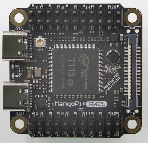
Here’s the photo from the MangoPi site: